S-11 Instructor
Preliminary translation
Index
4 The S-11, the first success after the war
5 Technical specifications and performance of the S-11
- Israel
- The National Aviation School
- America
- Italy
7 The S-11 at the LSK/Royal Air Force
- The S-11 at the MLD, Naval Aviation Service
9
doings and dealings
of the S-11
10 The S-11 is starting a second life
- Fokker Four
- NIV/TH Delft
- Boundary layer extraction
13 Overview of all built S-11s, M-416s, T-21s and T-22s.
1. Preface.
Hundreds of publications in the form of a magazine article or complete book have been written on the subject of “Fokker” for decades.
Enough reason with the rich history of the person Fokker, the various Fokker factories and the more than 200 Fokker aircraft types built, to devote (historical) articles to it.
Also, as long as Fokker aircraft are still active in aviation, Fokker aircraft will be published for years to come.
Over the years, dozens of articles have been written in national and foreign aviation magazines about one of the many aircraft types, the Fokker S-11 Instructor.
Not least because at the moment (2019) there are still ten S-11s in airworthy condition in the Netherlands and abroad and can be regularly seen at air shows as a historical element.
With this book I want to give as good a picture as possible about the construction and use of the S-11 as an elementary training aircraft for the then future pilots within various air forces in the 1950s and 1960s.
As with many projects within aircraft design and construction, the S-11 has not been free from deficiencies leading up to its operational use.
Fortunately, many of those obstacles were solved during the start of the build and the test program, a small number of shortcomings unfortunately remained.
The Fokker aircraft factory has spent years, before and during the production of the
S-11, in the staff magazine “Het trimvlak” reported on the construction, demonstrations, sale and use of the device.
A number of posted photos are unfortunately of a lesser quality, but in order to give the most extensive picture possible, they have been placed anyway, for history sometimes quantity comes first.
Amstelveen 17 June 2019.
Henk Amstelveen.
Hundreds of publications in the form of a magazine article or complete book have been written on the subject of “Fokker” for decades.
Enough reason with the rich history of the person Fokker, the various Fokker factories and the more than 200 Fokker aircraft types built, to devote (historical) articles to it.
Also, as long as Fokker aircraft are still active in aviation, Fokker aircraft will be published for years to come.
Over the years, dozens of articles have been written in national and foreign aviation magazines about one of the many aircraft types, the Fokker S-11 Instructor.
Not least because at the moment (2019) there are still ten S-11s in airworthy condition in the Netherlands and abroad and can be regularly seen at air shows as a historical element.
In my opinion, many complete books about the S-11 history have not been published, even though it was the first major success for Fokker immediately after the Second World War.
As with many projects within aircraft design and construction, the S-11 has not been free from deficiencies leading up to its operational use.
Fortunately, many of those obstacles were solved during the start of the build and the test program, a small number of shortcomings unfortunately remained.
The Fokker aircraft factory has spent years, before and during the production of the
S-11, in the staff magazine “Het trimvlak” reported on the construction, demonstrations, sale and use of the device.
This source of information was one of the reasons for me to write this book about the Fokker S-11 Instructor.
Amstelveen 17 June 2019.
Henk Amstelveen.
2. Starting up after the war.
May 5, 1945, the Netherlands was liberated after the second world war and started to rebuild the country and the industry.
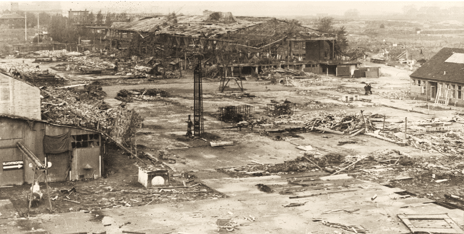
In fact, the Netherlands no longer had an aviation industry, the Fokker factory in Amsterdam North was largely destroyed and looted from 1944 by the Germans, who had transported most of the factory inventory to Germany.
For five years the Fokker factory had been under the coercion and supervision of the German occupying forces
worked on German aircraft, both new build and repair, plus the manufacture of parts for various German aircraft types.
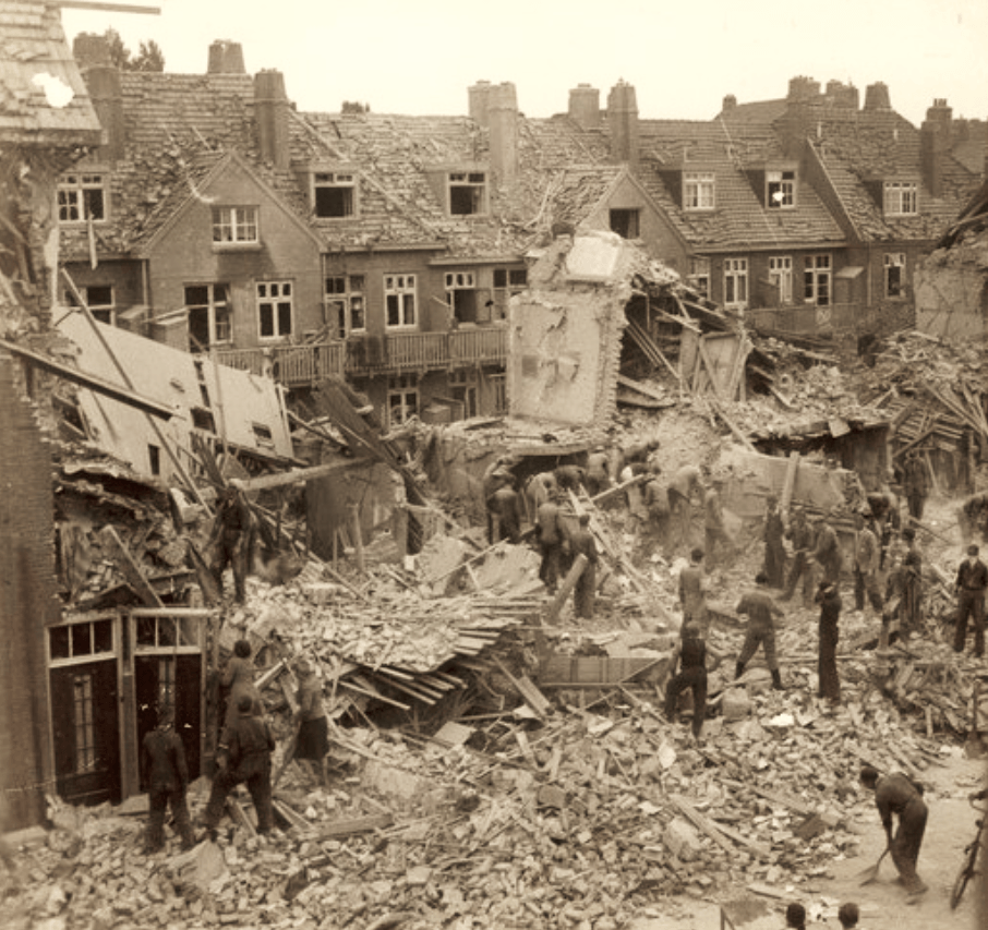
The partial damage that was still visible to the various factory hangars and buildings after the liberation, was caused by three bombings carried out by the Allies in 1943.
The Allies' argument was that they wanted to prevent war equipment being made for the Germans.
On July 17, 1943, the first bombing raid was carried out by the Americans, followed by a British bombardment on July 25, 1943 and finally a French bombardment on July 28, 1943.
May 5, 1945, the Netherlands was liberated after the second world war and started to rebuild the country and the industry.
In fact, the Netherlands no longer had an aviation industry, the Fokker factory in Amsterdam North was largely destroyed and looted from 1944 by the Germans, who had transported most of the factory inventory to Germany.
For five years the Fokker factory had been under the coercion and supervision of the German occupying forces
worked on German aircraft, both new build and repair, plus the manufacture of parts for various German aircraft types.
The partial damage that was still visible to the various factory hangars and buildings after the liberation, was caused by three bombings carried out by the Allies in 1943.
The Allies' argument was that they wanted to prevent war equipment being made for the Germans.
On July 17, 1943, the first bombing raid was carried out by the Americans, followed by a British bombardment on July 25, 1943 and finally a French bombardment on July 28, 1943.
Many of the bombs also landed on the area outside the Fokker factory in Amsterdam North, killing more than 200 innocent civilians.
On June 13, 1945, Mr. JE van Tijen
appointed by the Netherlands Management Institute as director of the Fokker factory.
mr. van Tijen was a real aviation man, with a pilot's license himself and had already worked at Fokker as a deputy director from 1936.
mr. van Tijen was fired from Fokker in 1941 by the German government because he did not want to cooperate with the German occupier.
mr. van Tijen was arrested twice by the Germans and from March 1943 he spent time in the German camp Buchenwald, where he was eventually liberated by the Americans.
Especially in the post-war construction of the Fokker factory, Mr. van Tijen has been a driving force in the production and development of aircraft and other products.

The Fokker factory was soon set up again by buying machines and tools in England, America and later also in Czechoslovakia.
Stolen inventory was also recovered from Germany.
In September 1945, the Dutch government indicated that it wanted in principle one Dutch aircraft industry, which should be a combination of Fokker,
Aviolanda and the aircraft construction department of the Scheldt Shipbuilding NV
This merger also came about on February 1, 1947 as, “Verenigde Nederlandsche Luchtenfabrieken Fokker io” (in formation).
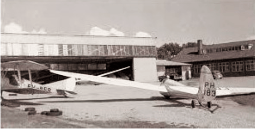
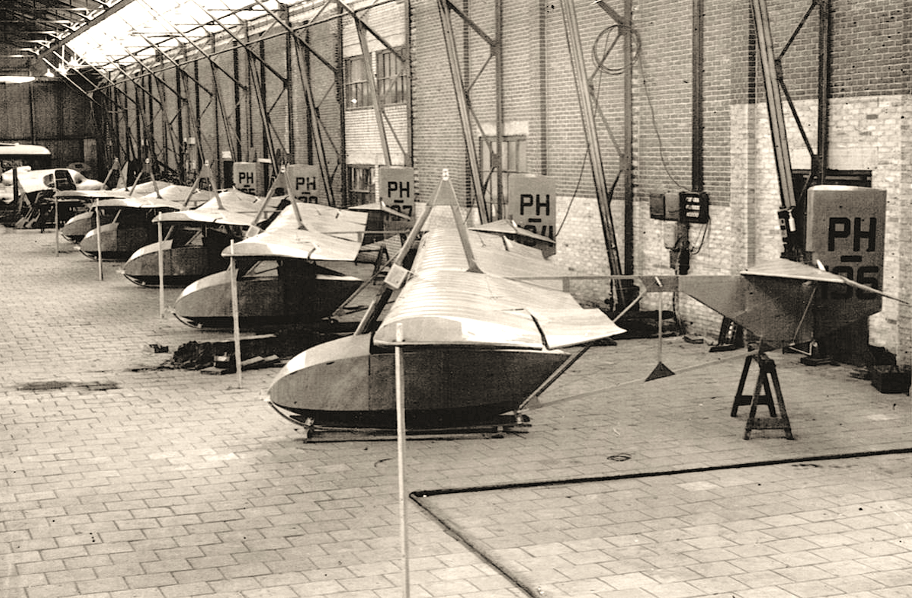
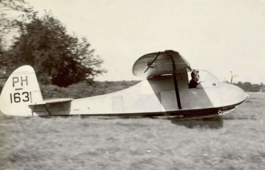
At the end of 1945, Fokker received the first serious order, an order from the Royal Dutch Aviation Association, KNVvL, to build 72 gliders (under license).
It concerned 36 ESGs, 24 Grunau Babies, 6 Olympias and 6 Goeviers.
Stolen inventory was also recovered from Germany.
In September 1945, the Dutch government indicated that it wanted in principle one Dutch aircraft industry, which should be a combination of Fokker,
Aviolanda and the aircraft construction department of the Scheldt Shipbuilding NV
This merger also came about on February 1, 1947 as, “Verenigde Nederlandsche Luchtenfabrieken Fokker io” (in formation).
At the end of 1945, Fokker received the first serious order, an order from the Royal Dutch Aviation Association, KNVvL, to build 72 gliders (under license).
It concerned 36 ESGs, 24 Grunau Babies, 6 Olympias and 6 Goeviers.
The airlines that had survived the war were not very financially strong.
Money for newly developed passenger aircraft was not available and Fokker also understood that developing a new passenger aircraft independently was not the first option.
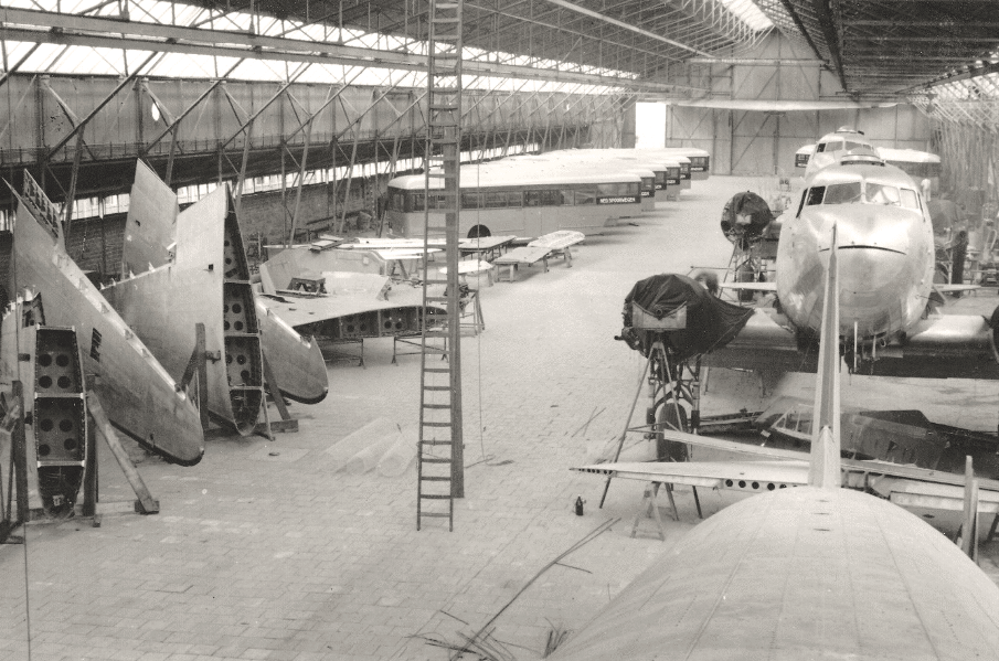
In order to meet the needs of passenger aircraft, Fokker,
immediately after the war many military DC-3 Dakotas and DC-4 Skymasters were converted into passenger planes.
An order of a very different nature in 1946 was that of the Dutch Railways to build 75 buses. Later on, various types and numbers of buses were built at Fokker for Dutch bus manufacturers.
The factory site has also been expanded with new sheds.
Money for newly developed passenger aircraft was not available and Fokker also understood that developing a new passenger aircraft independently was not the first option.
In order to meet the needs of passenger aircraft, Fokker,
immediately after the war many military DC-3 Dakotas and DC-4 Skymasters were converted into passenger planes.
Many DC-3s were converted into passenger aircraft for KLM, among others.
The factory site has also been expanded with new sheds.
3. The first post-war aircraft.
When working on DC-3s, buses and a number of other non-aviation related products, Fokker did think of developing, building and selling its own aircraft again.
Developing a new passenger aircraft was difficult, the market in Europe was provisionally supplied with revised DC-3s and DC-4s, plus that Fokker itself did not yet have the capital to develop large objects.
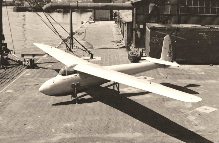
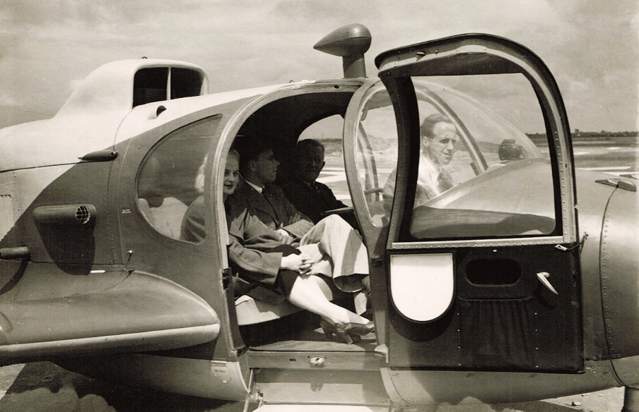
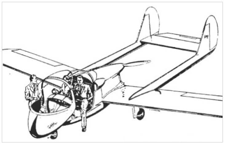
The F-25 was a low-decker with two tail booms behind the fuselage and was propelled at the rear of the fuselage by an engine with a push propeller.
The aircraft could be flown by one pilot and could carry three passengers.
The aircraft was not a success and in the end only 21 were built, some of which were not even completely ready to fly.
When working on DC-3s, buses and a number of other non-aviation related products, Fokker did think of developing, building and selling its own aircraft again.
Developing a new passenger aircraft was difficult, the market in Europe was provisionally supplied with revised DC-3s and DC-4s, plus that Fokker itself did not yet have the capital to develop large objects.
The first thoughts went to perhaps a new market in aviation: the business jet.
F-25
On May 16, 1946 Frits Diepen Aircraft NV placed an order for 100 F-25s, a four-seater business aircraft that was designed for Frits Diepen.
Diepen also had worldwide sales rights for the device.Frits Diepen aircraft NV was a trading company at Ypenburg airport near The Hague, with the aim of selling aircraft and aviation equipment, maintenance and repair of aircraft, transporting passengers by air taxis and everything related to this.
The aircraft could be flown by one pilot and could carry three passengers.
On October 20, 1946, the F-25 prototype made its maiden flight.

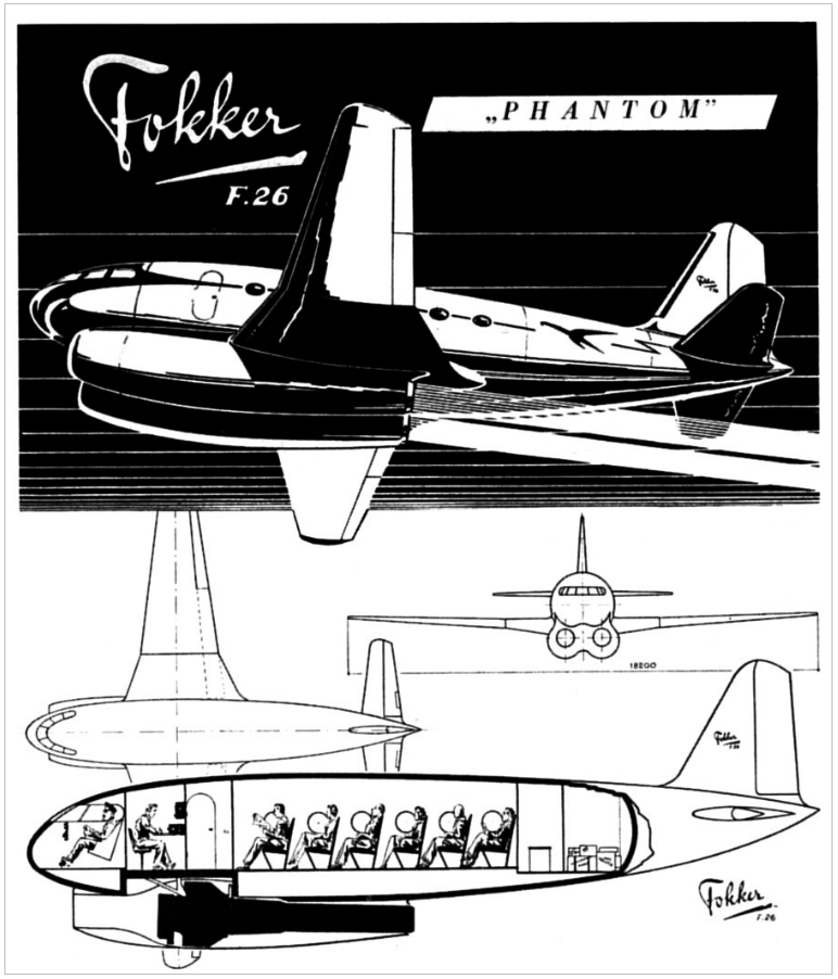
F-26 Phantom
The F-26 Phantom was also developed, a small aircraft powered by two jet engines for 16 passengers.
The 'design 232', as the F-26 was called internally, was designed under the direction of chief designer Marius Beeling. However, it was never built and thus did not progress beyond the drawing board, an artistic impression and a model.
P-1 Partner
Another design at the time was the P-1 Partner, a smaller version of the F-25.
The P-1 also only made it to a design on the drawing board and was never built.
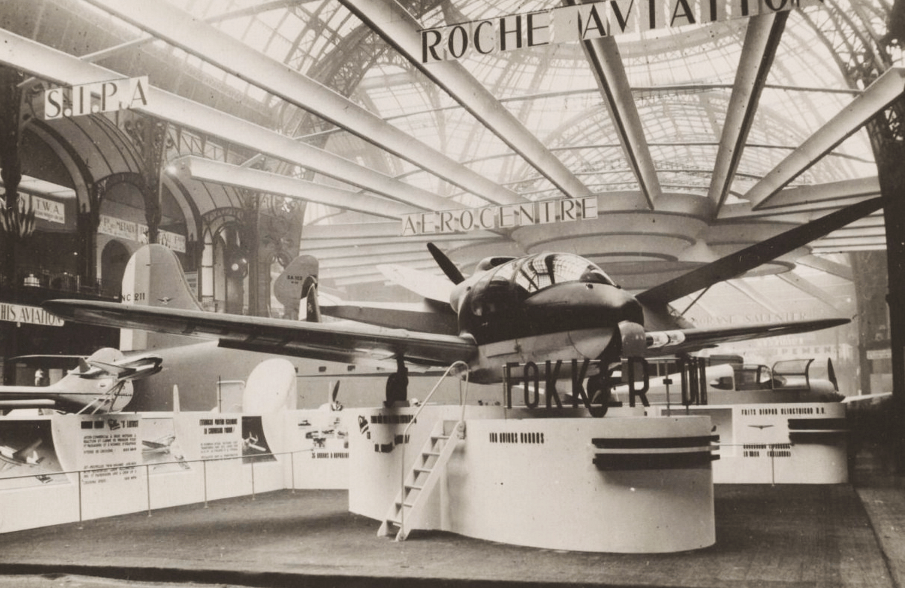
At the 17th International Aviation Exhibition in Paris in November 1946, the prototype of the F-25, plus impressions and models of the F-26 Phantom, the P-1 Partner and..... a model of the S -11 Instructor.
4. The S-11, the first success after the war.
The idea to develop a training aircraft arose partly because this need had not yet been met so shortly after the war.
The Tiger Moth biplanes used in the Netherlands for basic flight training date from the 1930s and were very outdated.
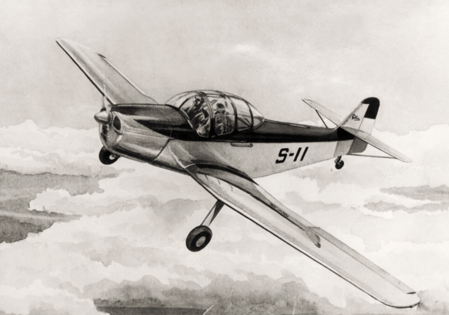
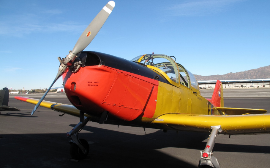
After a number of preliminary designs, design no. 223 at Fokker eventually resulted in the S-11 Instructor, as the aircraft was officially called. The "S" was the traditional designation for training aircraft types at Fokker.
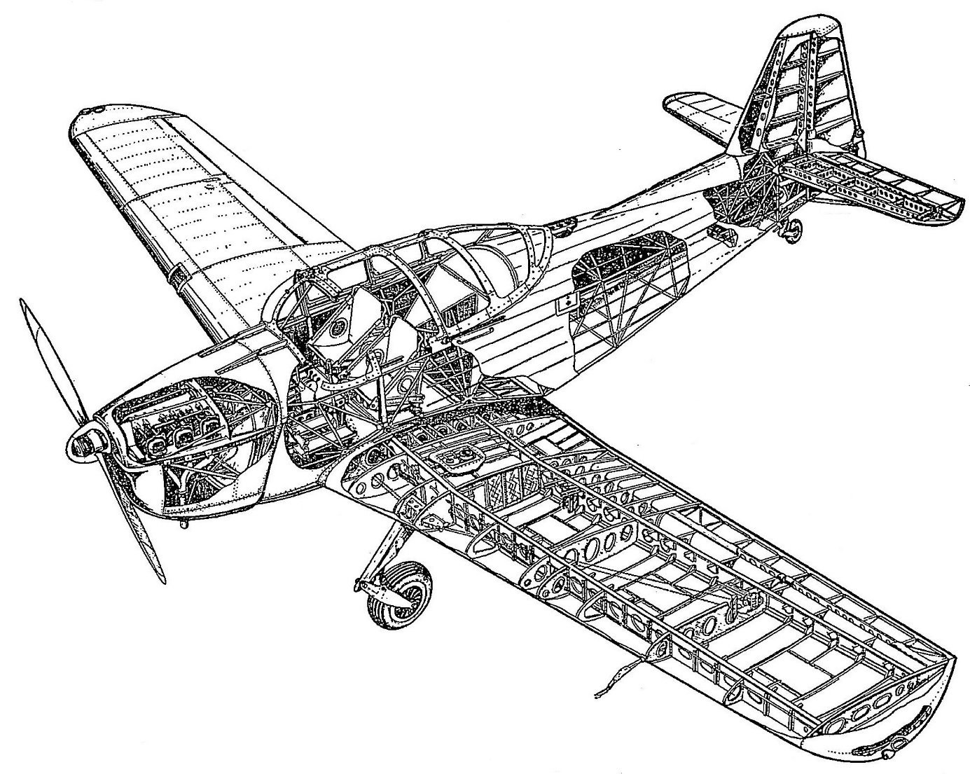
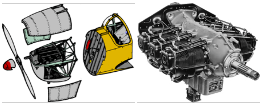
It would be a low-decker with a somewhat pre-war construction,
a hull of welded tubular steel, then partly clad in plywood and completely clad in linen, with an all-metal wing, vertical tail and horizontal stabilizer.
The direction and elevators mounted in the vertical tail and horizontal stabilizer were also covered with linen.
A buckled non-retractable landing gear was fitted under the wings and the cockpit seats would be side by side and not one behind the other, as was customary in a training aircraft until then.
The idea to develop a training aircraft arose partly because this need had not yet been met so shortly after the war.
The Tiger Moth biplanes used in the Netherlands for basic flight training date from the 1930s and were very outdated.
Partly because the Air Forces also renew their air fleet after the Second World War, there was interest in a new elementary training aircraft, also at the LSK. (LSK is the abbreviation of Air Forces, the name KLu did not exist yet)
It would be a low-decker with a somewhat pre-war construction,
a hull of welded tubular steel, then partly clad in plywood and completely clad in linen, with an all-metal wing, vertical tail and horizontal stabilizer.
The direction and elevators mounted in the vertical tail and horizontal stabilizer were also covered with linen.
A buckled non-retractable landing gear was fitted under the wings and the cockpit seats would be side by side and not one behind the other, as was customary in a training aircraft until then.
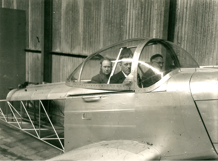
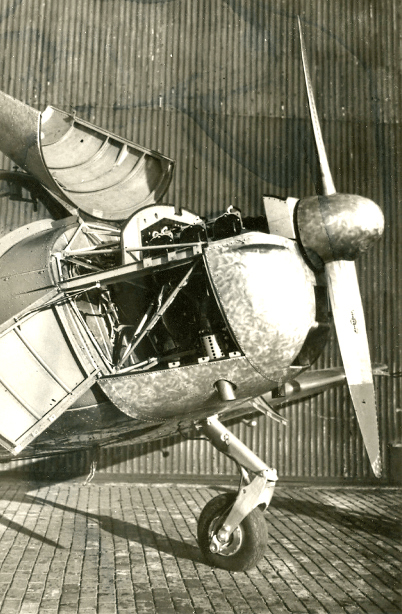
It soon became apparent that the application of a very spacious plexiglass hood would provide a good view from the cockpit.
The use of a tailwheel therefore had no adverse effects on the pilots' vision while taxiing.
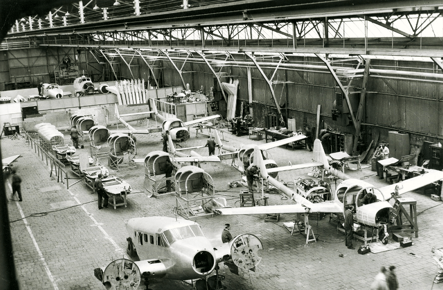
The success of this Fokker aircraft seemed to be assured when, before the prototype was built, in 1946 a sizeable order was received from Frits Diepen Aircraft NV for no fewer than 100 aircraft.
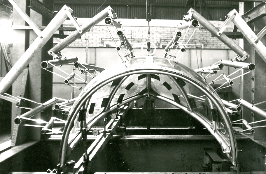
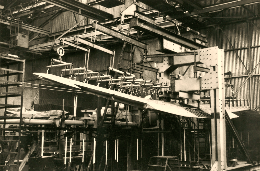
During the construction of the prototype, in 1947, the aircraft underwent a very large number of static load tests for that time. Especially the wing and plexiglass cockpit hood were subjected to many tests.
The use of a tailwheel therefore had no adverse effects on the pilots' vision while taxiing.
The cockpit was designed to be able to fly at night and there was room for two people next to each other and possibly one person in the back.
A 6-cylinder engine was used as the power source for the aircraft Lycoming 0-435-A
built-in boxer engine with a power of 190 hp, on which, initially, a two-bladed wooden propeller was mounted.
Frits Diepen saw a market of 70 units to private individuals, 10 units for the LSK, 10 units for the Indies Military Aviation and 10 units for the National Aviation School.
None of this came to fruition, the sales of these 100 S-11s were completely different.
Using a massive model of the S-11, aerodynamic studies were conducted in the NLL wind tunnel, National Aviation Laboratory.
In the spring of 1948, tests were also carried out in the vertical wind tunnel of the French “Institut de Mecanique des Fluides” in Lille.
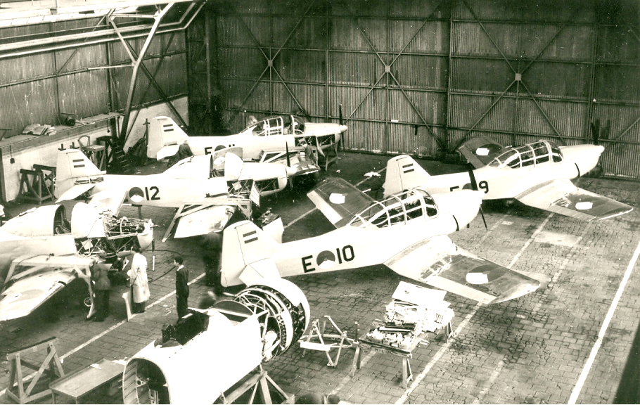
Extensive product checks during the building process of the S-11 on all parts, an extensive final check on the aircraft and (a number of) test flights, ultimately guaranteed a properly safe aircraft.
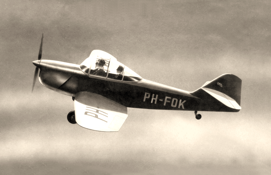
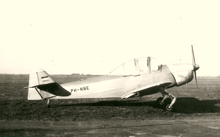
Towards the end of 1947, the first prototype could then go on a test run, before making its successful maiden flight on December 18, 1947 with Fokker's then test pilot at the controls. Gerben Sonderman.
It was not until January 1948 that the aircraft was registered in the Dutch civil aviation register, where it was assigned the registration PH-NBE.
In the spring of 1948, tests were also carried out in the vertical wind tunnel of the French “Institut de Mecanique des Fluides” in Lille.
Extensive product checks during the building process of the S-11 on all parts, an extensive final check on the aircraft and (a number of) test flights, ultimately guaranteed a properly safe aircraft.
Towards the end of 1947, the first prototype could then go on a test run, before making its successful maiden flight on December 18, 1947 with Fokker's then test pilot at the controls. Gerben Sonderman.
It was not until January 1948 that the aircraft was registered in the Dutch civil aviation register, where it was assigned the registration PH-NBE.
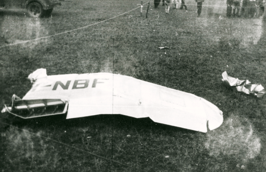
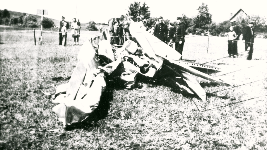
The second prototype, the PH-NBF, unfortunately crashed near Vedby in Sweden on June 16, 1949 during a demonstration for the Swedish Air Force.
The plane was flown by two Swedish instructor pilots, despite the fact that the S-11 is fully suitable for making so-called aerobatics or Aerobatics, the pilots probably overestimated this.
The pilots were unaware of the maximum forces that could be applied to the S-11 during aerobatics.
Incidentally, these so-called strength calculations were in the documentation that was handed to them.
While accelerating from a steep dive, the left wing broke and folded over the cockpit.
In the impact to the ground, both pilots were killed and the aircraft was completely destroyed.
After this accident, various reinforcements were added to the construction of the S-11.
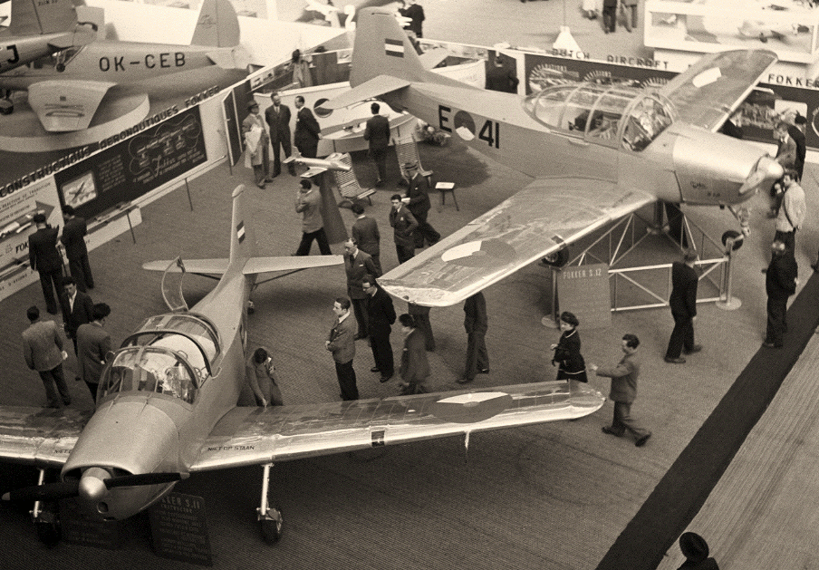
The third S-11 prototype was built in the Fokker factory as S-12 and registered as PH-NDC.
The S-12 was a modified version of the S-11 with a nose wheel and rearward main landing gear, plus several other changes.
Yet it has only remained with the prototype, the S-12 was not built further in the Netherlands, later under license in Brazil as a T-22.
The S-12 did have the Air Force registration E-41 for a while and could also be seen in this trim at the Paris salon in 1949.
The S-12 as such was never in service with the Air Force.
In the first months of 1948, Fokker held discussions in Portugal about the possible sale of the S-11, or possibilities of license construction in Portugal.
Unfortunately, neither of these options came to fruition.
In early 1949, the S-11 was demonstrated for the British Royal Air Force at Hullavington Air Force Base.
The RAF pilots were very satisfied with the S-11, but also criticized a number of points, including the construction of the plexiglass cockpit hood, they would have liked part of the hood to be thrown off in an emergency. .
In its early days, the S-11 was widely demonstrated and flown for many interested parties of all kinds.
The marketing of Fokker products at the time was already well organised.
One of the first demonstration flights for a large audience took place on 10 July 1948 during the festive post-war opening of Hilversum airport.
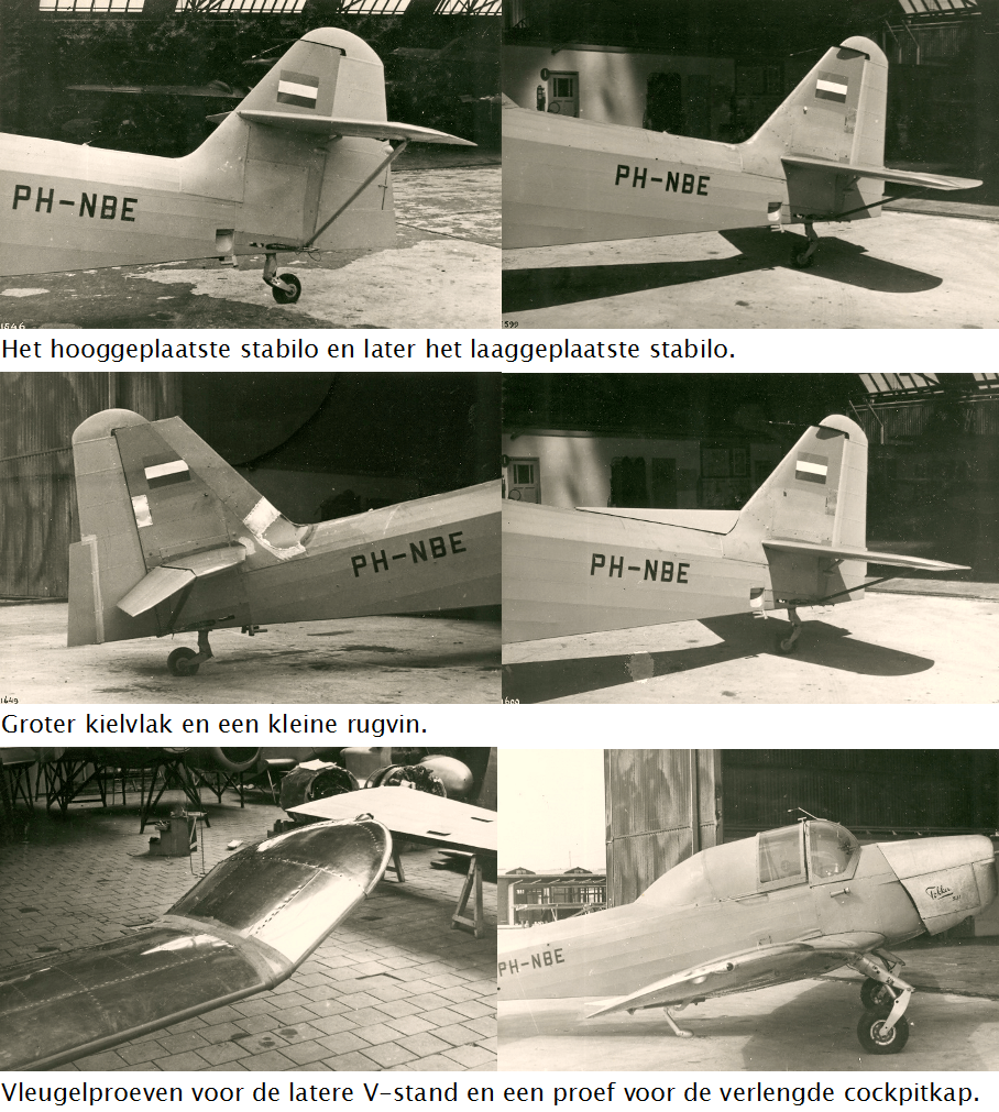
During the start-up phase of the construction of the S-11 and during the first test flights, there were so-called teething problems, especially the lateral stability caused problems.
By the end of 1948 all problems had been solved.
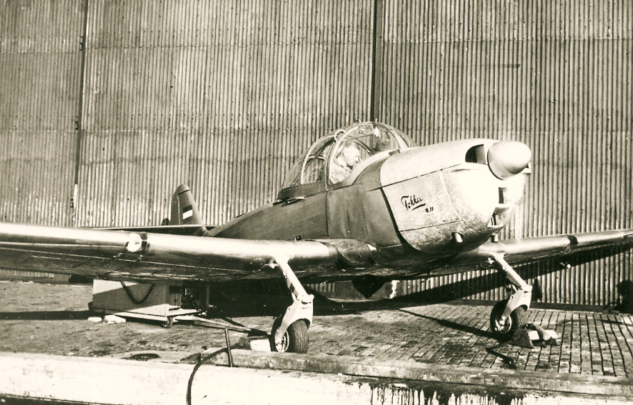
The changes the aircraft had undergone before it took its final shape were a longer Plexiglas cockpit cover, of which only a small part has to be slid away to enter the aircraft, a larger V-shape of the wings, a lower stabilizer , a significantly larger vertical fin and rudder and finally the mounting of a small dorsal fin.
The changes the aircraft had undergone before it took its final shape were a longer Plexiglas cockpit cover, of which only a small part has to be slid away to enter the aircraft, a larger V-shape of the wings, a lower stabilizer , a significantly larger vertical fin and rudder and finally the mounting of a small dorsal fin.
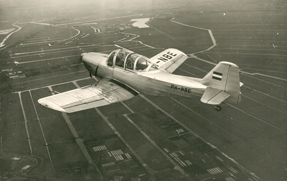
For example, on February 17, 1949, in a bright spring sun at Ypenburg airport near The Hague, the S-11 was flown and presented to the Dutch press with Fokker's test pilot Gerben Sonderman in the cockpit.
In a period after that many skilled foreign pilots were allowed to try out the S-11, after having done this usually critically, they were also very satisfied with the qualities of the S-11.
In a period after that many skilled foreign pilots were allowed to try out the S-11, after having done this usually critically, they were also very satisfied with the qualities of the S-11.
5. Technical Specifications and Performance of the S-11.
General data.
The S-11 is intended as a training aircraft for basic pilot training and is fully Aerobatic for making aerobatics.
With regard to those aerobatics, the aircraft was then classified in category IIIa
according to the concept of Dutch Airworthiness Regulations 1940, whereby the following aerobatics were allowed to be carried out:
a. sharp bend.
b. walk backwards.
c. Immelmann.
d. slow roll.
e. toll flight.
f. short back flight.
g. dive and further aerobatics performed by a combination of the above
aerobatics can be created without the aircraft being overloaded.
The Immelmann, is a to Max Immelmann the aforementioned flight maneuver, which he performed as a pilot in the First World War with a Fokker monoplane aircraft.
It starts from horizontal flight, then a half loop is made, after which a half roll follows and the aircraft flies horizontally again.
High loads are understood to mean those loads that may not be intentionally exceeded during normal use.
In all flight conditions, including dives, the maximum engine/propeller speed must not exceed 2550 (Aeromatic propeller).
Exceeding this can lead to disintegration, the disintegration of the propeller blades.
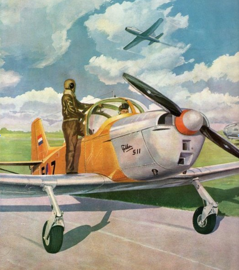
The S-11 has two seats next to each other, the right one is for the instructor and the left one for the student pilot.
The advantage of this is that the instructor can see all the actions of the student pilot and thus better instruct and assess.
Behind the two seats is space for the storage of 15 Kg. luggage, possibly installing a radio system, etc.
In the beginning when the S-11 came into being, this place was designated as a seat for a third person.
At the back left of the Plexiglas shade, a hinged opening was initially also constructed for this purpose, which was later discontinued.
The chairs of the instructor and the student are suitable for a so-called sitting parachute, which the pilots carry under their butts with belts over their flying everywhere.
The aircraft is a cantilever monoplane with a low-mounted one-piece wing.
It has a pull propeller, a fixed main landing gear, a tailwheel and a 6 cylinder air-cooled boxer engine of the type Lycoming 0-435-A, with an output of 190 hp.
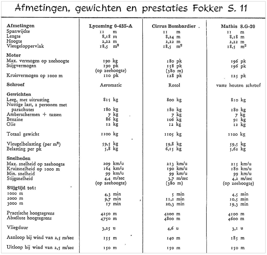
Before choosing the Lycoming engine, we also looked at the Cirrus Bombardier engine with a power of 180 hp, the Mathis 8.G-20 engine with a power of 196 hp and the De Havilland Gipsy Major with a power of 144. hp.
General data.
The S-11 is intended as a training aircraft for basic pilot training and is fully Aerobatic for making aerobatics.
With regard to those aerobatics, the aircraft was then classified in category IIIa
according to the concept of Dutch Airworthiness Regulations 1940, whereby the following aerobatics were allowed to be carried out:
a. sharp bend.
b. walk backwards.
c. Immelmann.
d. slow roll.
e. toll flight.
f. short back flight.
g. dive and further aerobatics performed by a combination of the above
aerobatics can be created without the aircraft being overloaded.
The Immelmann, is a to Max Immelmann the aforementioned flight maneuver, which he performed as a pilot in the First World War with a Fokker monoplane aircraft.
It starts from horizontal flight, then a half loop is made, after which a half roll follows and the aircraft flies horizontally again.
High loads are understood to mean those loads that may not be intentionally exceeded during normal use.
In all flight conditions, including dives, the maximum engine/propeller speed must not exceed 2550 (Aeromatic propeller).
Exceeding this can lead to disintegration, the disintegration of the propeller blades.
The S-11 has two seats next to each other, the right one is for the instructor and the left one for the student pilot.
The advantage of this is that the instructor can see all the actions of the student pilot and thus better instruct and assess.
Behind the two seats is space for the storage of 15 Kg. luggage, possibly installing a radio system, etc.
In the beginning when the S-11 came into being, this place was designated as a seat for a third person.
At the back left of the Plexiglas shade, a hinged opening was initially also constructed for this purpose, which was later discontinued.
The chairs of the instructor and the student are suitable for a so-called sitting parachute, which the pilots carry under their butts with belts over their flying everywhere.
The aircraft is a cantilever monoplane with a low-mounted one-piece wing.
It has a pull propeller, a fixed main landing gear, a tailwheel and a 6 cylinder air-cooled boxer engine of the type Lycoming 0-435-A, with an output of 190 hp.
Before choosing the Lycoming engine, we also looked at the Cirrus Bombardier engine with a power of 180 hp, the Mathis 8.G-20 engine with a power of 196 hp and the De Havilland Gipsy Major with a power of 144. hp.
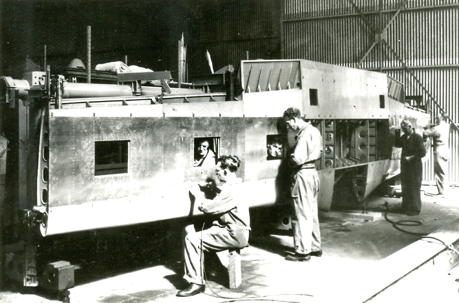
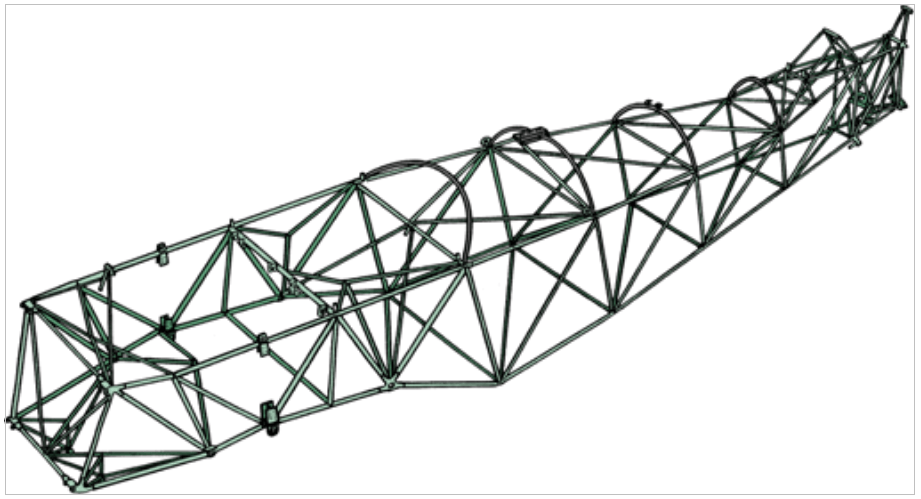
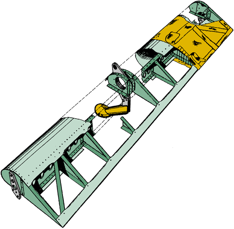
The construction
hull
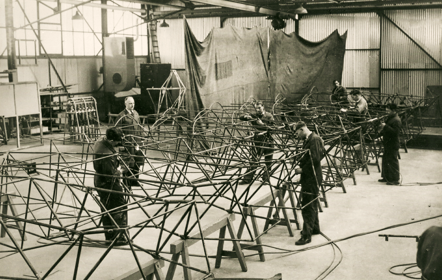
The hull is made of welded carbon steel tube, a so-called truss construction.
The tubes were autogenously welded by hand, there are nodes where as much as 9
pipes come together
At the front of the hull, up to the fire bulkhead of the engine, plywood sheets have been installed on the left and right.
The entire hull including the plywood is covered with linen.
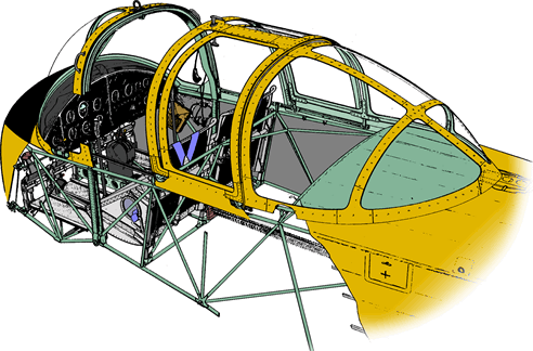
On the front of the fuselage on top of the cockpit, a large Plexiglas hood is mounted, which consists of three parts, the windshield, the sliding hood and the fixed hood.
The windshield, the front part of the hood, also has the function of a transfer trestle, a weighted construction that, if the aircraft were to lie upside down, would not be pressed in and the pilots could leave the aircraft.
Two amber colored screens can be fitted on the inside of the windshield for blind flying.
Behind the windshield, a part of the hood can be opened so that the pilots can enter the cockpit.
In the left side of the fuselage above the rear of the wing is a first aid kit.
The first aid kit is accessible through a hatch in the fuselage.
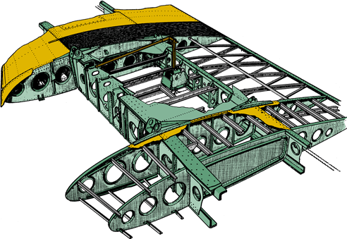
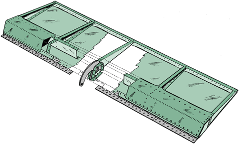
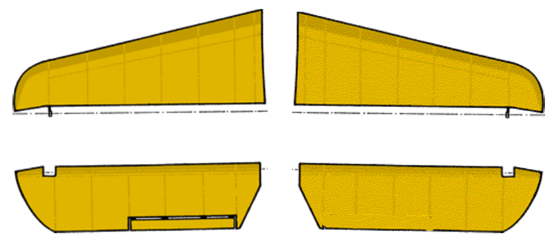
Wing
The wing is built as one piece of aluminum and is tapered in shape, the ailerons and flaps are installed in the wing.
During the wing construction, parts were glued in some places, a process that would later be widely used on the F-27 Friendship at Fokker.
Gluing aircraft components was already used in 1937 by the English aircraft manufacturer Handley Page.
Two Goodyear Pliocel fuel tanks with a capacity of 70 liters each are fitted in the wing on either side of the fuselage.
The wing houses the fuel lines, aileron cables and brake lines.
The wing is equipped with access panels in various places to be able to carry out internal maintenance and repairs.
On the wing, against the fuselage, there are rubber anti-slip pockets on the left and right for safe entry into the cockpit.
The ailerons are of aluminum construction, covered with linen.
The aluminum wing flaps mounted at the rear of the wing are of the "split valve" type and are mechanically operated by a lever between the cockpit seats.
The valves have three positions, close, take-off, landing.
Grimes navigation lights are located on the wing tips, Grimes landing lights are mounted in the wing nose on the left and right.
In the left wing nose is the pitot tube.
stabilo
The stabilizer consists of two parts, mounted at the rear of the hull, each with a support post at the bottom.
At the rear of the stabilizer, on the left and right, are the elevators of an aluminum construction covered with linen.
The operation takes place by means of cables.
The left elevator has a trim tab, adjustable from the cockpit.
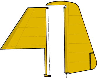
vertical tail
The keel is made of aluminum, with a small dorsal fin on the hull at the front, also made of aluminum.
The vertical rudder mounted in the vertical fin is of an aluminum construction covered with linen and is operated by means of cables.
The rudder is provided with a trim tab at the bottom, which can be adjusted manually on the ground.
With the S-11s delivered to Israel, and the M-416 built under license at Macchi, the trim tab could be adjusted from the cockpit.
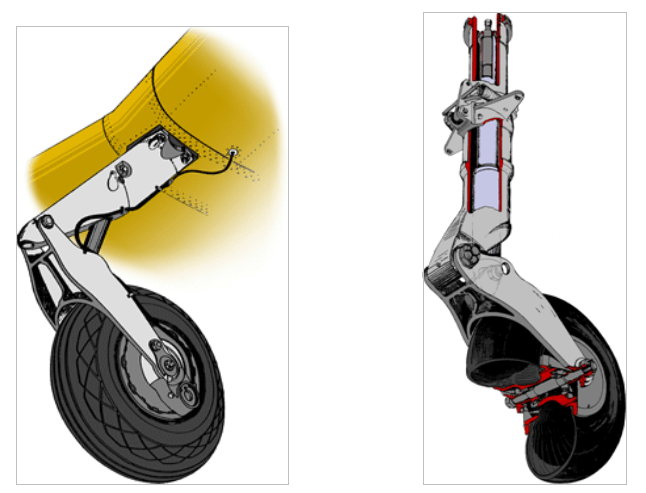
Landing gear
The landing gear consists of two main wheels and a tail wheel, the landing gear is not retractable, the main wheels are placed in a bent shape under the front of the wing.
The width between the main wheels is 2.85 mtr. and of the Olaer type, the wheels and tires are from the manufacturer Goodyear.
The tailwheel is resiliently steerable, the steering can be disengaged so that it can be rotated 360°.
The main wheels are hydraulically braked, simultaneously or individually, from the pedals located in the cockpit.
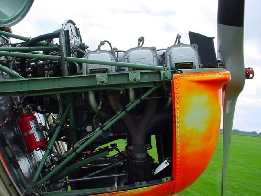
The engine
The engine is of the type Lycoming 0-435-A with 6 horizontally located cylinders and gives a power of 190 hp.
The engine is equipped with the following necessary parts:
a. a carburetor, type Marvel.
b. two Scintilla magnets.
c. a starter, type Delco-Remy.
d. a gas pump, model GP-8897.
e. a generator, type Delco-Remy.
f. a hub for the wooden propeller.
g. vacuum pump, type Pesco.
The engine trestle is made of welded carbon steel tubing and is easy to attach to the fuselage frame with four points against the firewall.
The motor is easily accessible for maintenance by opening two side panels with so-called quick shutters.
After that, the top cover can be opened without effort if necessary.
The engine compartment is also equipped with a fire extinguishing system that is filled with methyl bromide that can extinguish any engine fire via pipes and nozzles.
The fire extinguisher can be operated by the pilots from the cockpit.
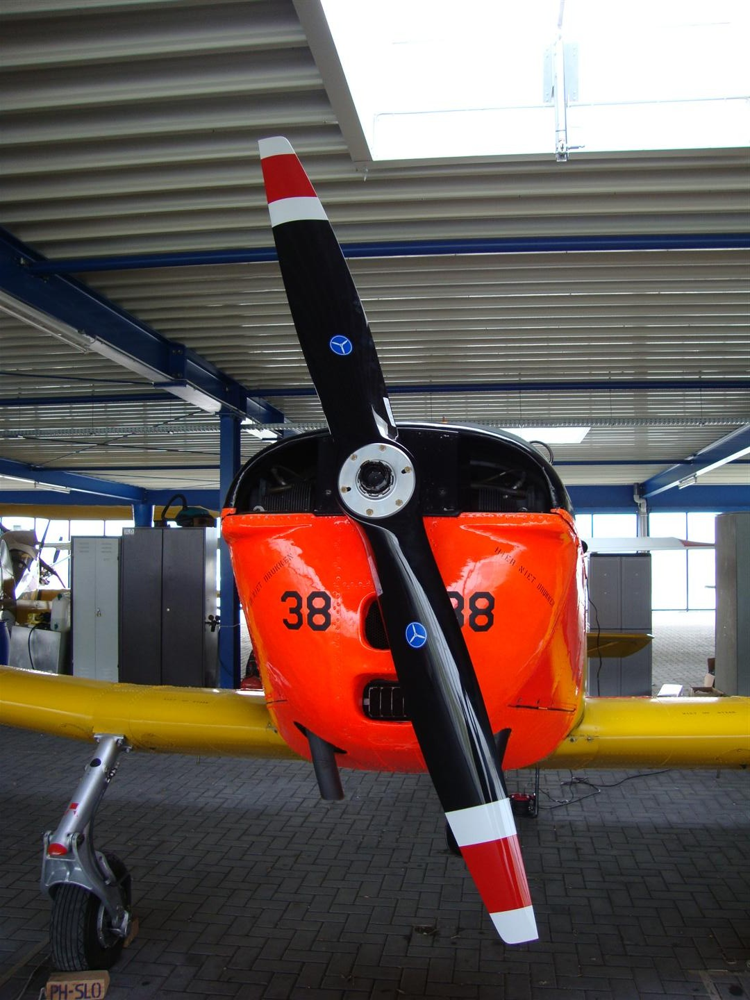
Mounted on the hub of the motor is a two-bladed wooden propeller of the type FDV 2015 manufactured by Industrie Maatschappij Avio-Diepen in The Hague, the prototypes had a Sensenich propeller type 85RW55.
Due to the poor climbing performance with this propeller, the KLu quickly replaced it with an automatically adjustable one Koppers Aeromatic model 220 propeller, which was later fitted by other S-11 users as well.
These propellers were later banned by the Dutch Aviation Authorities due to the occurrence of hairline cracks in propeller components.
After that, almost all S-11s were equipped with a fixed Hoffmann HO-33 propeller.
In addition to these 3 propellers used, other propellers were later mounted on the S-11, including another model from Avio Diepen.
A different propeller model can often be seen on foreign registered S-11s.
A so-called spinner is placed over the wooden propeller on the hub,
the aluminum egg-shaped spinner provides better aerodynamic properties.
About the Aeromatic propeller a spinner could not be fitted, over the Hoffmann it was possible, but in practice this did not happen often.
The motor is easily accessible for maintenance by opening two side panels with so-called quick shutters.
After that, the top cover can be opened without effort if necessary.
The engine compartment is also equipped with a fire extinguishing system that is filled with methyl bromide that can extinguish any engine fire via pipes and nozzles.
The fire extinguisher can be operated by the pilots from the cockpit.
Mounted on the hub of the motor is a two-bladed wooden propeller of the type FDV 2015 manufactured by Industrie Maatschappij Avio-Diepen in The Hague, the prototypes had a Sensenich propeller type 85RW55.
Due to the poor climbing performance with this propeller, the KLu quickly replaced it with an automatically adjustable one Koppers Aeromatic model 220 propeller, which was later fitted by other S-11 users as well.
These propellers were later banned by the Dutch Aviation Authorities due to the occurrence of hairline cracks in propeller components.
After that, almost all S-11s were equipped with a fixed Hoffmann HO-33 propeller.
In addition to these 3 propellers used, other propellers were later mounted on the S-11, including another model from Avio Diepen.
A different propeller model can often be seen on foreign registered S-11s.
A so-called spinner is placed over the wooden propeller on the hub,
the aluminum egg-shaped spinner provides better aerodynamic properties.
About the Aeromatic propeller a spinner could not be fitted, over the Hoffmann it was possible, but in practice this did not happen often.
The Cockpit
The two seats in the cockpit are adjustable and equipped with a safety belt over the abdomen and over both shoulders.
For both pilots there is a control stick for operating the elevators and ailerons.
In front of the pilots on the floor of the cockpit are the pedals for operating the rudder, also the pedals are linked to the tail wheel.
Additional pedals are also fitted to the pedals for operating the brakes.
To the left of the cockpit are the throttle, gas mixture and trim tab adjustment levers.
In the center in front of the instrument panel is a column with handles for
trim tab adjustment, gas, carburetor air heating and petrol hand pump.
To the right of the cockpit is a chart index.
Outside of the instrument panel are the instruments, the fuel tap,
tailwheel decoupling, the Bendix starter, parking brake and a lever for adjusting the rudder/brake pedals.
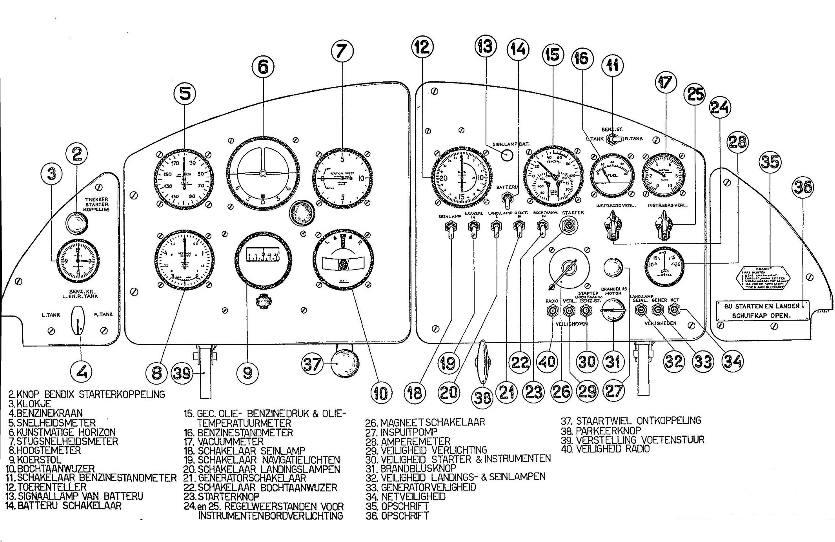
In front of the pilots is the four-piece instrument panel with the following instruments and controls.
On the left panel are:
1. starter control button.
2. a timepiece.
3. the fuel tap.
For the left pilot a panel containing:
1. speedometer.
2. artificial horizon.
3. ascent speedometer.
4. altimeter.
5. course indicator.
6. turn indicator.
For the right pilot a panel containing:
1. tachometer.
2. Combined oil pressure, oil temperature and fuel pressure gauge.
3. fuel gauge.
4. ammeter.
5. starter button.
6. magnetic switch.
7. injection pump.
8. front switches, navigation lights, instrument panel lights, etc.
9. various fuses.
10. vacuum gauge.
There are no instruments by default on the panel placed on the right.
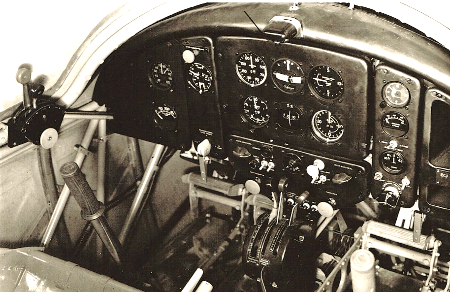
The cockpits of the prototypes PH-NBE and PH-NBF, were fitted with six small instrument panels.
The two seats in the cockpit are adjustable and equipped with a safety belt over the abdomen and over both shoulders.
For both pilots there is a control stick for operating the elevators and ailerons.
In front of the pilots on the floor of the cockpit are the pedals for operating the rudder, also the pedals are linked to the tail wheel.
Additional pedals are also fitted to the pedals for operating the brakes.
To the left of the cockpit are the throttle, gas mixture and trim tab adjustment levers.
In the center in front of the instrument panel is a column with handles for
trim tab adjustment, gas, carburetor air heating and petrol hand pump.
To the right of the cockpit is a chart index.
Outside of the instrument panel are the instruments, the fuel tap,
tailwheel decoupling, the Bendix starter, parking brake and a lever for adjusting the rudder/brake pedals.
In front of the pilots is the four-piece instrument panel with the following instruments and controls.
On the left panel are:
1. starter control button.
2. a timepiece.
3. the fuel tap.
For the left pilot a panel containing:
1. speedometer.
2. artificial horizon.
3. ascent speedometer.
4. altimeter.
5. course indicator.
6. turn indicator.
For the right pilot a panel containing:
1. tachometer.
2. Combined oil pressure, oil temperature and fuel pressure gauge.
3. fuel gauge.
4. ammeter.
5. starter button.
6. magnetic switch.
7. injection pump.
8. front switches, navigation lights, instrument panel lights, etc.
9. various fuses.
10. vacuum gauge.
There are no instruments by default on the panel placed on the right.
The cockpits of the prototypes PH-NBE and PH-NBF, were fitted with six small instrument panels.
A large Smith Hughes compass is placed between the seats and the column in the cockpit.
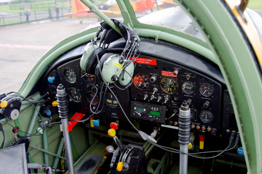
There was no built-in radio as standard, during operational use at the Royal Netherlands Air Forces, UHF radios were built into the S-11 in the 1960s at Aviolanda at Woensdrecht Air Base.
The still airworthy S-11s currently have (other) radios built in, often in the bottom of the right instrument panel.
The power supply is provided by a 12 Volt DC generator directly driven by the engine.
The S-11 is equipped with a 12 Volt battery, placed in the center wing, in front of the vehicle in front under the cockpit hood.
Right in the fuselage above the wing is a so-called “External power”
connection.
A separate aggregate can be connected to the ground to start the engine or to have on-board voltage on the systems without putting a load on the battery.
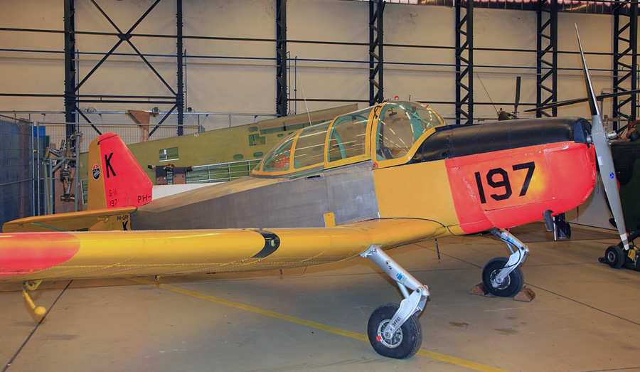
paint scheme
The tubular steel hull, motor trestle and all steel installation parts of the hull and motor trestle, were sandblasted and provided with a layer of red lead followed by a matt green topcoat.
Most of the light metal, aluminum parts were anodized (a galvanic coating to prevent corrosion), then a primer coat, followed by the same matte green topcoat as over the steel parts.
For example, the entire inside of the S-11, including the cockpit, had a calm matt green appearance, the wings, stabilizer, vertical tail, etc. also had the same matt green color internally.
A number of other light-metal aluminum parts were degreased with per chlorine and then also provided with a primer with the matt green topcoat layer.
The instrument panels were satin black, plus all control knobs were color-coded in the cockpit.
The linen covering the hull, rudder, elevators and ailerons was provided with four layers of red dope.
This originally transparent cellulose lacquer was pigmented with (red) deadhead pigment and was applied with a wide flat brush, the rest of the lacquer layers were sprayed.
The red dope stretched the linen tight after drying and filled the very small holes in the linen to a tight and smooth surface.
Two layers of aluminum cellulose lacquer followed over the red dope. The aluminum lacquer had, among other things, the function of protecting the linen against UV radiation.
The final color on the outside differed per customer, but also on the basis of a cellulose lacquer at the time.
Up to and including the aluminum layer, was the standard paint scheme of the S-11.
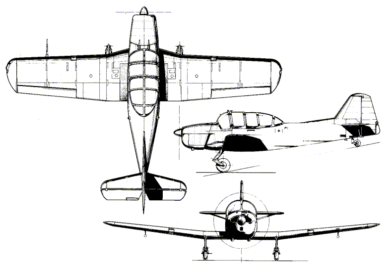
Wingspan 11 m
Length 8.18 m
Height 2.22 m
Wing area 18.5 m²
Wing V-rack 6° 30'
Engine Lycoming 0-435-A
Maximum power 190 hp
Cruising speed power 110 hp
Propeller (standard wood) FDV 2015, diameter 2.15 m
Curb weight with standard equipment 810 kg
Practical weight, 2 kites with parachute 180 kg
Fuel 98 kg
Oil 12 kg
Maximum take-off weight 1100 kg
Maximum speed at sea level 209 km/h
Cruising speed at sea level 164 km/h
Minimum speed 99 km/h
Climbing speed to 1000 meters 5.6 min
Climbing speed to 2000 meters 13.4 min
Climbing speed to 3000 meters 25.4 min
Practical flying height 3850 m
Maximum flight altitude 4450 m
Maximum flight time 3 hours 55 min
Takeoff length, wind 2.5 m/sec 195 m
Landing length, wind 2.5 m/sec 155 m